Office sources of high quality fibre have been hit by increased work-from-home across the world. Here Mark Christopher, global market development manager – tissue, Buckman, explains how deink plants can turn lower quality fibre into a viable option.
With the recent global shutdowns and work from home edicts being applied across vast swaths of the global economy, the sorted office pack (SOP) waste stream which is preferred by tissue makers has been significantly impacted. The reduction in office-based work has resulted in much less SOP being created and available for collection.
This reduction in supply is tempered somewhat by the concurrent reduction in demand for AfH tissue products, which is the predominant user of recycled fibre streams like SOP. Many companies began a significant stockpiling of SOP furnish during the early stages of the shutdowns in anticipation of potential shortages which created a tighter supply early and is now resulting in an easing of demand as they begin to draw down their inventory.
The situation is highly variable and other producers are finding it difficult to source SOP or they can only do so at elevated prices. This then forces them to consider less uniform and more highly contaminated sources of recycled fibre. Moving to lower quality recycled furnishes puts pressure on the deink plant to maintain brightness, dirt and stickies levels without sacrificing yield.
Doing so relies on three key functions of the deink plant: detachment of ink from the fibre, separation of the ink and contaminants from the fibre stream, and finally rejection of the ink and contaminants. This paper will examine these key process steps and provide guidance on how to optimise them.
Ink detachment
Ink detachment predominately takes place in the pulper. The bales of collected paper are placed into the pulper along with clarified process water, and mechanical energy is applied to create rotor-to-fibre and fibre-to-fibre friction that separates them from each other as well as separating the coatings and inks from the fibre surface. This is critical because it is not possible to remove ink through the rest of the process unless it has been first detached from the fibre. Along with fibre exiting the pulper, there are two types of ink:
1. Free ink: detached ink free floating in the slurry which now has the potential to be separated and rejected.
2. Bound ink: ink that remains attached to the fibre surface or has been trapped within the fibre lumen.
It stands to reason that the more ink we can detach from the fibre, the higher the potential final brightness that can be achieved. Driving detachment in the pulp is not a linear benefit curve due to two detrimental impacts of longer pulper times:
1. Longer pulper times in the pursuit of increased detachment reduce throughput. The negative financial impact of this is obvious.
2. More time in the pulper does not just detach more ink but serves to break down the ink, coating and contaminants into smaller and smaller particle sizes. This in turn makes the removal of the particles across screening and flotation more difficult. The water soluble and the very smallest of these ink particles can actually be absorbed into the lumen of the fibres along with the water as they hydrate and swell. (1) This results in a darkening of the fibre that is irreversible.
The ideal situation for the operator is to be able to get as much ink detached as quickly as possible.
The most common practice for balancing pulper output with ink detachment is to add a deinking surfactant chemistry into the pulper. The surfactant provides three benefits:
1. It acts as a penetrant drawing water with it. This speeds up disruption of the surface coatings and the hydrogen bonding structure of the base sheets, facilitating the breakdown of the bales into a pulp slurry.
2. It segregates ink and contaminants, preventing their redeposition on the surface.
3. It envelops very small ink particles, preventing them from being adsorbed into the fibre lumen and causing irreversible fibre darkening.
By removing more ink and segregating it, the brightness ceiling of the pulp is increased, resulting in higher final brightness even at equal ink removal efficiencies.
Other parameters than can be adjusted to impact detachment in the pulper include:
• Temperature: higher temperature will speed up the pulping process.
• pH: higher pH, often achieved via the addition of caustic or even bicarbonate, will speed up the process. However, higher pH has been proven to disperse stickies.
Optimising your pulping operation while monitoring ink detachment efficiency as outlined above allows for higher potential final brightness of your pulp by reducing bound ink concentration.
Having detached the ink from the fibre, we must now separate it, and other contaminants, from the fibre stream. Deinking plants are designed with various processes to remove all types and sizes of contaminants.
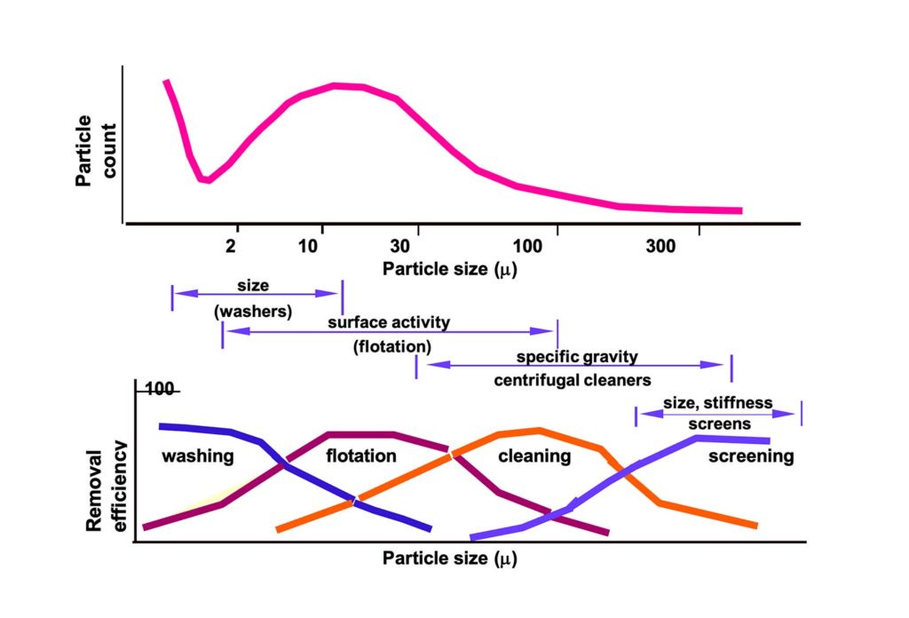
The most commonly employed process steps and their relative efficiencies at removing contaminants based on their nature and size are depicted in the diagram from Richard Venditti from NCSU (Figure 1).
Screening and cleaning
The screening and cleaning unit operations of the deink plant separate contaminants from the fibre slurry based on size and weight respectively.
They are typically set up in cascading banks such that rejects are re-screened/re-cleaned in several steps to further ensure concentration of the contaminants and reduce yield loss. Particles that have a specific gravity greater or lower than water can be effectively rejected with cleaning stages, but this does not include ink and many stickies.
Low consistency slotted screening is considered to be the best approach for stickies removal by screens, and this is the approach most mills employ (3). These screens will be able to separate most contaminants including stickies which are larger than the nominal slot size, but ink and stickies smaller than this threshold will pass through. Even larger stickies particles can extrude through screen holes and slots that are smaller than the stickies particle itself (6).
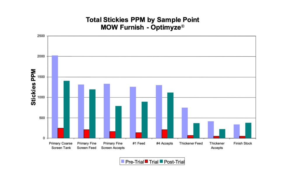
Another methodology often applied to address these stickies in the deink plant is with enzymatic technology that breaks down and changes the surface characteristics of the stickies, rendering them more hydrophilic.
This approach has been successfully applied for over 20 years in the recycled operations of pulp, packaging and tissue mills. Because enzyme technology is specific, other chemistries and operations are not impacted. Operational benefits include increased ink detachment and significantly reduced stickies counts in the pulp as shown in the mill application below (Firgure 2).
Flotation
The flotation deinking process works by using air bubbles floated through a pulp suspension. Hydrophobic contaminants like ink and stickies within the pulp slurry preferentially attach to these bubbles as they rise to the top of the suspension. This results in a concentration of the undesirable contaminants within a foam layer at the top of the flotation cell.
The number of bubbles and their size distribution within both the pulp slurry and the foam layer which sits on top impacts ink removal efficiency and yield loss (2).
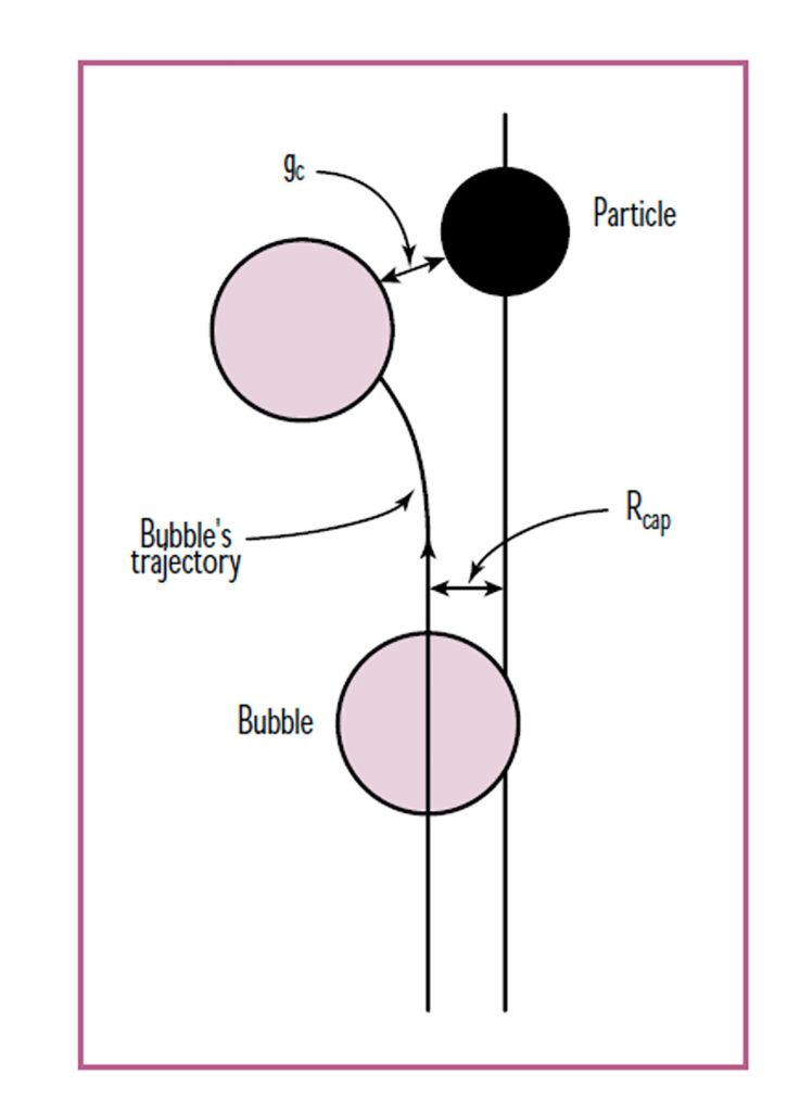
Let us consider the bubble/contaminant interaction: As a bubble approaches a particle to within a certain minimum distance, which we denote as the “critical gap,” gc, then it is assumed that strong attractive forces take over via a range of methods whereby bubble/particle attachment takes place as depicted in the Figure 3 (4).
Proper optimisation and operation of the air system and its injectors is important in order to ensure high specific air volume. Bubble structure and stability in the cell froth, which is rejected, impacts yield as well. Highly stable foam bubbles do not allow floated fibre to drop down through the foam froth and back into the cell for acceptance. When no surfactant is employed, the air bubbles still float ink, but the resulting froth is much more stable. This often has the effect of driving lower cell level set points which reduces ink rejection or more fibre carryover which reduces yield.
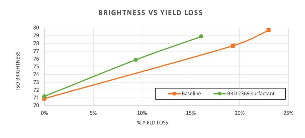
Modern deinking surfactants are intended to not just improve the repulping process but carry through to the flotation cells where they contribute to more efficient collection of ink by the air and a foam froth that breaks down more easily. The effect is the ability to get higher brightness at lower equivalent yield loss as shown in the Figure 4.
An often ignored benefit of flotation is the highly effective removal of stickies from low quality pulp. We have already explained how the basic mechanism of flotation is one driven by hydrophobic forces, and stickies are highly hydrophobic particles. Application of the correct deinking surfactant in the cells improves stickies collection and rejection in these systems. It has been shown by Tinna Sarja that upwards of 80% of microstickies can be removed via flotation (7).
Specific air volume (SAV) is defined as the volume of air per unit mass of solids in the flotation cell feed, generally expressed as cm3/gms or L/Kg. We can see that changing either the air volume or the cell consistency will result in a change in the SAV. Depending on the floatation equipment design, the operator may or may not have the ability to impact air volume, but all operations can dictate targeted consistency of operation of the cells.
The importance of this will become apparent as we examine how to most effectively concentrate the ink and other contaminants in the reject stream such that we can maintain brightness at lower overall yield loss.
It has been shown by Peters and Romigio (5) that improved concentration of ink can be obtained at high flotation cell operating consistencies as long as the SAV can be increased along with it. In other words, maintaining and improving ink removal at higher flotcell consistencies requires ever larger volumes of air.
Yield considerations
Although ash losses via flotation are not as sensitive to cell consistency, applying the approach above, which increases SAV, will increase ash loss via flotation. This is generally less of a concern for the tissue maker because it is overridden by the benefits of the overall pulp quality, and the reduced ash content in itself provides benefits.
• Ash content preserved across flotation will be rejected in subsequent washing steps.
• Ash content pushed forward to the machine is extremely difficult to retain in the high sheer, low consistency forming process used by tissue machines.
• Ash retained in the sheet reduces perceived softness and increases dusting.
Washing
One or more washing stages may be present within a deink plant layout. A washing stage in a deink plant is technically just a thickening stage, although depending on the plant configuration, a clarified water source may be used to dilute the stock just prior to the thickening stage. In washing, ink and contaminant removal efficiency is a function of the percent increase in consistency across the stage. A washer
that takes a pulp slurry from 1% consistency to 2% consistency has removed 50% of the water. If we assume the ink was evenly dispersed in the water and no mat filtering occurred, we would expect a 50% ink removal. Of course, depending on the design of the equipment, different amounts of mat filtering are exhibited, and as such larger particles of ink and contaminants are trapped within the mat and not rejected here.
Washing operation efficiency can be improved via the following mechanisms:
1. Reducing inlet consistency. Almost invariably, lower inlet consistency into a washing stage will result in greater consistency increase across the stage (greater fraction of ink separated) as well an improvement in the removal at the larger particle end of the removal spectrum.
2. Dispersing surfactants, which can break down ink particles or enzymatic stickies technology which can reduce stickies size range, improve washing efficiency of both.
Rejection of the contaminants
Having detached and separated the contaminants from the pulp substrate, we must now reject them from the system. Some stages, like secondary flotation rejects, may be sent directly to effluent. Other reject streams may employ a thickening stage(s) to maximise water recovery and reuse and minimise disposal costs of the rejects fraction. This is commonly done via a DAF operation treated with a polymeric program to maximise the quality of the reclaimed clarified water stream.
The DAF rejects themselves may be sent to a further thickening stage such as a screw press. These systems are often referred to as the kidneys of the deink plant. It is important to monitor and control the quality of the clarified water streams as they will be reintroduced into your system.
When water systems are contaminated with ink or stickies, problems with quality and operational efficiency will result. The objective is for the contaminants to leave mill with minimal loss of fibre or water.
Understanding what each operational unit is designed to accomplish – whether it is pulping, screening, cleaning or other operation – and determining the efficiency of each pays easy dividends.
With careful attention to detachment, separation and removal of contaminants, lower quality fibre sources are now a viable option thus easing the burden of the constant search for higher quality fibre. A properly operated deink plant relies on a good design, proper operation of the equipment and the proper use of chemistry.
Sources
1. Ackerman,C; Putz, H.J.; Gottsching,L. Deinking of water-born flexo inks by flotation. Pulp & Paper Can. 95 (8): T307-T312 (1993).
2. Emerson, Ian Zachery. Particle and Bubble Interactions in Floatation Systems. Dissertation. Auburn University. https://etd.auburn.edu/bitstream/handle/10415/98/EMERSON_ZACHERY_45.pdf?sequence=1
3. I Jokinen H, Ämmälä A, Virtanen JA, Lindroos K & Niinimäki J (2006) Effect of bar geometry on screen plate performance – a laboratory study on pressure screening. Nordic Pulp and Paper Research Journal 21(4): 451-459.
4. RONGGEN PAN, FRITZ G. PAULSEN, DONNA A. JOHNSON, DOUGLAS W. BOUSFIELD, AND EDWARD V.THOMPSON. Global model for predicting flotation efficiency Part 1: model results and experimental studies. VOL. 79: NO. 4 TAPPI JOURNAL.
5. Henry Peters, Tom Remigio, Tim Evans and Marc Degenais. Interaction of Flotation Cell Operating Variables. http://www.tappi.org/content/events/07recycle/papers/peters.pdf
6. Flanagan, J., Venditti, R. A., Jameel, H., Lucas, B. E. 2002. The Passage of Pressure Sensitive Adhesives Through a Single Slot. Progress in Paper Recycling, 11(3): 17-23.
7. Sarja, T.. “Measurement, nature and removal of stickies in deinked pulp.” (2007).
This article was written for TWM by Mark Christopher, global market development manager ñ tissue, Buckman.