By Nalco’s Michael Murcia, Mita Chattoraj, JC Ye, Steve Hoefs
 Dissolved air flotation (DAF) units are used throughout the paper industry for solids / liquid separation in process and primary wastewater treatment applications. The performance of these DAFs is often left to manual control schemes that are dependent on the operations staffs’ ability to recognise and adjust their treatment strategy in response to changes in influent loading demand. Failure to make the necessary operational adjustments can lead to decreased solids capture and poor effluent water quality, causing downstream operational concerns; plugged showers, filters, overloaded secondary treatment systems, exceeding discharge limits, etc. To improve overall DAF performance, a comprehensive monitoring and control system is needed to manage the performance of this critical mill asset.
Nalco has developed 3D TRASAR™ Technology for DAF operations which utilises advanced sensors, feed forward/feedback control algorithms and a sophisticated cleaning methodology to ensure reliable real time data collection and chemical control for the DAF. This system improves effluent water quality and consistency while optimising the DAF total cost of operation (TCO). Through customer case histories, the presentation will review the actual performance results achieved through use of this technology.
- Improved DAF effluent quality and consistency
- Maximised recycle / reuse opportunities for DAF effluent
- Overall optimisation of total cost of operation for the DAF, which includes a reduction in manual intervention of plant operations, optimization of chemistry, and reduction of downstream upsets
Dissolved air flotation units (DAF) are used throughout the paper industry for solids / liquid separation. Within the DAF system, compressed air and chemical separation aids (coagulants/flocculants) are used to assist in the separation (flotation) of solids and contaminants from the incoming process stream. Many DAF systems are treated with both a coagulant to neutralise system charge and a flocculant to aggregate small particles to larger flocs. However, depending on the nature of the process stream, some systems will use only a coagulant or flocculant as a separation aid. When dosed properly, the separation aids create large particles from the small, finely dispersed suspended solids which float to the top and are removed from the DAF.
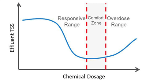
Unlike some chemical additives, simply increasing the concentration of a separation aid in a DAF will not always result in a reduction in suspended solids of the DAF effluent. While it is necessary to dose some coagulant and/or flocculant to properly neutralise the charged elements in the process stream and allow proper flocculation, over-dosing these additives can result in charge reversal, resulting in the stabilisation of the small, colloidal solids. Therefore, there is an optimum range of chemical additive concentration that leads to separation, where above and below this range will result in poor suspended solids separation in a DAF (Figure 1).
DAF effluent upsets from the under or over feeding of separation aids can lead to a variety of operational problems. In cases where the DAF effluent is being reused in replace of fresh water on machine showers, filters, process make-up water supply, etc, additional TSS loading can cause nozzle or filter plugging. In the case where the effluent is discharged to the wastewater treatment plant, swings in TSS from the DAF can lead to unstable biological treatment in the secondary treatment plant and possible fines from permit violations and unnecessary surcharges from high solids discharge.
The control of separation aid dosing in DAFs today is typically highly manual, requiring a high degree of operator involvement. Coagulant and flocculant demand will vary with changes in the incoming water quality. As a result, operators struggle with trying to keep pace with these system changes, resulting in effluent water quality variability and upsets. Because of the nonlinear response of the coagulant /flocculant separation aids, operators frequently overdose chemistry in response to system upset further compounding the effluent water quality concerns.
Attempts have been made to automate separation aid addition using flow-based chemical control strategies that maintain a given chemical concentration across a variable system load based upon volume. However, this technique does not take into account changes in system charge demand, which can produce incomplete charge neutralisation or charge reversal resulting in variability in effluent water quality.
A variety of online measurement techniques have been developed to assist in the monitoring of DAF influent and effluent water quality. However, one of the major obstacles in monitoring the solids loading online is the accuracy of the measurement in the harsh conditions where sensor fouling and system entrained air can render the measurements useless. Such online sensors are often installed and subsequently abandoned when it is found that they require too much maintenance to keep clean or are generating inaccurate data.
However, in plants where online monitoring of the DAF effluent is reliable and accurate, signals generated by the sensors are often used simply to monitor the DAF performance. The complexity of using the online readings and identifying the proper separation aid dose without under or over dosing requires advanced algorithm logic beyond what is typically used in industrial PLCs (PID). Utilising simple PID control in an application that can experience under and over dosing inevitably leads to over dosing, charge reversal and poor DAF effluent quality.
Further complicating the development of an automated control strategy is the variable lag time from when a swing in water quality or flow rate will be sent to the DAF and when it will begin to impact the effluent quality. This time lag can range from a couple minutes to an hour depending on how the DAF is set up, making standard control strategies difficult to tune to properly compensate for the delay time.
Commercial automation offerings to date have proven to be largely ineffective or overly maintenance intensive due to the nonlinear nature of chemical demand in wastewater, as well as the high potential for sensor fouling (Gerry, 2002; Zhen, 2009; Vanrolleghem, 2003 ;Harremoës, 1993 and Scully, 1998). Therefore, availability of a cost effective system that delivers automated, reliable, performance-based control of chemical addition for Paper DAF systems has been an unmet need.
AUTOMATION APPROACH – 3D TRASAR Technology for DAF operations
Reliable measurement of DAF effluent quality is essential to determine the necessary chemical dose needed in the DAF. With the objective of developing an automation system platform that can be used in DAF systems in a variety of industries and water streams, Nalco developed 3D TRASAR Technology for DAF operations. Given that the DAF process is designed to separate suspended solids (Rickard, 1917) and that suspended solids scatter light (Briggs, 1962), turbidity was selected as the universal water quality measurement to determine DAF performance.
The 3D TRASAR Technology for DAF systems analyse the DAF effluent and optionally influent, depending on the control strategy selected, to optimise the separation aid addition to maintain the DAF effluent at a predetermined turbidity level. The approach contains a number of unique features that allow for accurate / reliable system monitoring and control.
To address a common problem of sensor fouling experienced by most online measurements in a high solids process stream, several features were built into the system to improve reliability and reduce the need for maintenance. For the optical turbidity measurement, a 3D TRASAR turbidimeter was developed for this offering, which is capable of measuring a range of turbidity from 0-8000 NTU, spanning the majority of industrial DAF applications.
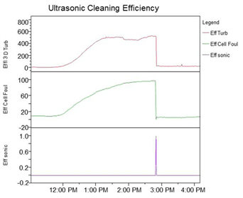
Understanding that any level of deposit formation on the turbidimeter surface could compromise reading accuracy, a unique ultrasonic cleaning approach was developed to periodically clean the turbidimeter. In addition to the automated ultrasonic cleaning, the 3D TRASAR turbidimeter has the capability to measure the degree of fouling on the optical sensor’s surface. This ability allows the ultrasonic cleaner to be triggered on demand based on a threshold level of fouling measured by the 3D TRASAR turbidimeter, ensuring the turbidimeter remains clean and reports accurate readings. This fouling measurement is also important when the system is in automated control. In the event the fouling builds up to a critical level and the ultrasonic cleaning system is unable to remove the deposit, a fouling alarm is generated, and the control of chemical dosage is put into a fail-safe operation until the turbidimeter is serviced and the alarm cleared.
In cases where the influent stream contains large particles that could interrupt flow through the system, an automated solution was developed to remove blockages from the instrument plumbing. Automated pneumatic ball valves are used to isolate the instrument plumbing and compressed air is subsequently injected to back-purge the system to remove any blockages that stop the sample from flowing. As is the case for ultrasonic cleaning, the compressed air purge is controlled by the 3D TRASAR controller. However, just as the integrated fouling measurement is used to trigger ultrasonic cleaning, an onboard flow metre is used to identify the loss of sample flow from a blockage in the instrument and trigger a compressed air purge to restore sample flow.
When sampling process water streams from pressurised pipes or in the effluent of the DAF, it is common to have some entrained air present in the water. These air bubbles scatter light similarly to suspended solids, creating an offset in the online turbidity reading, which is interpreted as artificially high solids loading. To prevent these bubbles from contributing to the turbidity readings taken by the 3D TRASAR turbidimeter, a plumbing arrangement was developed that uses the natural buoyancy of the air bubbles as a means of separating air from the sample stream being measured before the turbidity measurement is taken.
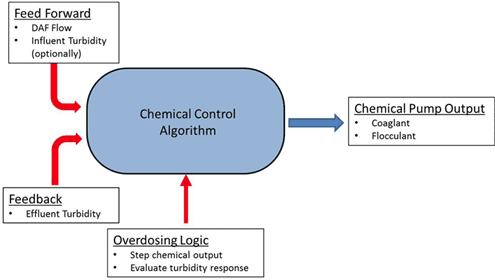
With an instrument that reliably and accurately measures the water quality in the DAF operation, Nalco developed a chemical control algorithm that uses a combination of feed forward and feedback signals to optimise separation aid control. The feed forward portion of the control is designed to change the chemical dosage rate as a function of the instantaneous changes in DAF flow and optionally turbidity loading in the DAF influent. If the chemical demand in waste streams was always proportional to the flow and incoming TSS loading, feed forward control alone would be sufficient to produce a consistent DAF effluent quality. However, due to the changing nature of the suspended solids and the differences in the ability of the DAF designs to handle variable hydraulic loading rates, as well as other mechanical variables, there is a need to adjust the chemical dosing based on the final DAF effluent quality. Therefore, a feedback component is present in the control algorithm. The contribution of the feed forward and feedback elements to the chemical dosage calculation is automatically adjusted in the 3D TRASAR algorithm to provide a consistent DAF effluent quality.
In addition to feed forward and feedback signals contributing to the chemical dosage calculation, another layer of logic is used in the control algorithm to determine whether an upset in the DAF effluent is due to either under or over dosing. In the event of an upset, the 3D TRASAR overdosing logic will adjust the chemical dosage while feed forward and feedback controls are running and observe the response in effluent turbidity. Based on the response in effluent turbidity, the 3D TRASAR over dosing logic can determine the whether the upset requires more or less chemical to correct.
Data from the sensors is collected by the onboard 3D TRASAR controller, which has flexibility to accept and send external signal information to and from the mill DCS. Data collected by the 3D TRASAR controller can be monitored 24/7 by the Nalco 360™ Service team where the information is examined for trends, downloaded to create automated system performance reports, and used to provide alarm notification to a pre-determined contact list on system upset, such as high effluent turbidity.
The following case studies highlight the use of 3D TRASAR Technology for DAF as part of Nalco’s comprehensive plan to improve DAF effluent water quality.
Case Study 1
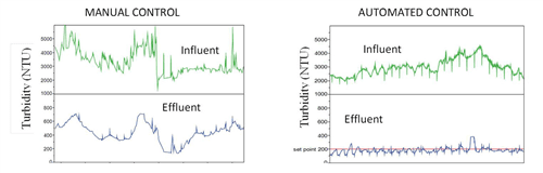
A North American tissue mill had a corporate initiative to reduce their fresh water consumption. They had identified the DAF effluent as a possible source of water to be reused back into their process but they knew that they would need to improve the quality and consistency of this effluent stream if it were to be reused. Previously the DAF effluent was being sent to the waste water treatment plant for additional processing. Under manual control, the mill was able to achieve an effluent water quality of 426 +/- 132 NTU turbidity. The mill had determined that to bring the DAF effluent back into the process would require the water quality to be improved to a turbidity level no greater than 200 NTU.
Working with the mill, Nalco, after confirming that the proper settling aid program (coagulant/flocculant) had been selected, incorporated the 3D TRASAR Technology for DAF system to assure optimal settling aid dosage was achieved at all times in response to system demand changes. Through use of the appropriate chemistry and the 3D TRASAR technology, the average effluent turbidity was reduced to 172 +/- 31 NTU (Figure 5).
The reduced variability and improved effluent water quality allowed the mill to reuse the DAF effluent back into their process displacing fresh water. This resulted in a reduction of fresh water requirements by 36 million gallons per year, representing a $500k/year annual savings to the mill.
Case Study 2
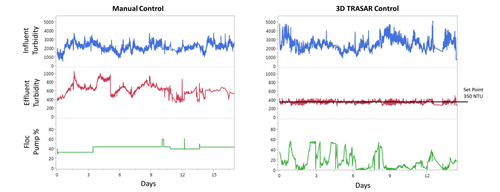
A North American 100% recycled paperboard mill wanted to improve the performance of their DAF system while looking for ways to reduce the mill VOC footprint. The mill had used a base loaded chemical strategy for their DAF flocculant addition making adjustments based upon the cleanliness of the DAF post filter and paper machine shower nozzles. Working with Nalco, the mill reviewed the use of dry polymer chemistries to replace their current liquid flocculant program. Prior to running any dry polymer evaluations, Nalco incorporated the 3D TRASAR Technology for DAF into the current programme. Not only was the 3D TRASAR technology able to improve the DAF effluent quality and reduce the variability, it was also able to deliver an optimised concentration of separation aid reducing the overall consumption and minimizing the VOC contribution to the plant from this application. Figure 6 highlights the frequency and degree of flocculant pump adjustments made by the 3D TRASAR system in response to changing system demands and desired effluent water quality objectives.
SUMMARY AND CONCLUSIONS:
Constantly changing process water streams processed by industrial DAFs create a challenge for operators to identify the optimum dosage of coagulant and flocculant needed to achieve the desired DAF performance. This inherent variability paired with the nonlinear nature of the relationship between chemical dose and DAF effluent quality creates an opportunity for automating the chemical dosage based on real-time performance monitoring. This unmet need for automating chemical dosing in DAF systems was addressed with the development of 3D TRASAR Technology for DAF. Specific features such as ultrasonic cleaning, compressed air blockage removal and sensor fouling readings have been critical in enabling the development of an automated chemical control method by providing consistent, reliable operation of the instrument. Results achieved through the use of 3D TRASAR Technology for DAF include reduction in discharge surcharges, improved DAF effluent variability, reduction in total cost of operation, improved operator productivity, optimised chemical consumption, and the opportunity to reuse the consistently cleaner DAF effluent in the process.
By Michael Murcia, staff scientist, Wastewater Solutions, Nalco; JC Ye, marketing manager, Wastewater Solutions, Nalco; Mita Chattoraj, corporate scientist, Core Automation, Nalco; Steve Hoefs, senior industry development manager, Paper, Water Utilities and Recovery, Nalco
[box] REFERENCES
Briggs, R. (1962). Continuous recording of suspended solids in effluents. Journal of Scientific Instruments, 39(1), 2.
Gerry Carty,G. O’Leary,Matthew Crowe, (2002). Water Treatment Manuals: Coagulation, Flocculation and Clarification. Environmental Protection Agency, 85p, ISBN-10: 1840950900.
Harremoës, P., Capodaglio, A.G., Hellström, B.G., Henze, M., Jensen, K.N., Lynggaard-Jensen, A.,Otterpohl, R. and Soeberg, H., (1993). Wastewater treatment plants under transient loading – performance, modeling and control. Wat. Sci. Tech., 27(12), pp71-115.
Rickard, T. A., & Ralston, O. C. (1917). Flotation. Mining and Scientific Press.
Scully, P., (1998). Optical Techniques for Water Monitoring. Monitoring Water Quality, Elsevier. pp15-35.
Vanrolleghem P.A. and Lee D.S. (2003). On-line monitoring equipment for wastewater treatment processes: state of the art. Water Science and Technology, 47 (2) pp1-34.
Zhen Lianga, b, Yanxin Wangb, Yu Zhoub, Hui Liub. (2009). Coagulation removal of melanoidins from biologically treated molasses wastewater using ferric chloride. Chemical Engineering Journal, 152 (1), 1 October, pp88-94.[/box]
3D TRASAR, Nalco 360, Ecolab, Nalco and the logos are trademarks of Ecolab USA Inc. (c)2014 Ecolab USA Inc. All Rights Reserved